The line and load wires are important parts of the switches and outlets. It is important to distinguish them for safer wire connections. But how do you differentiate them? That’s what I will share in this article.
The line wire carries power from the main source to the outlet, and the load wire transfers it to the connected devices in the circuit. The line wire runs from the service panel to the first device, while the load wire moves the power from the first to the second, and so on.
As a beginner, it will be common for you to confuse and mix the two. So, our article represents the difference between the two wires, how to identify them, and their applications.
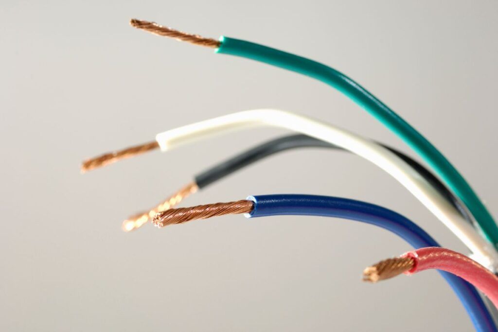
Check out our list of top-handpicked products for all your electrical, appliance, and HVAC system needs to keep your home running smoothly.
This post includes some affiliate links.Understanding the basics of electrical wiring and circuitry
Electrical wiring and circuitry are the backbones of electrical systems.
The electrical circuit is a constant loop that carries current from your house’s main panel and transfers it to the appliances throughout the house.
Multiple switches, outlets, fixtures, and other appliances can be connected to a single circuit.
The three main wires used in electrical wiring are hot, neutral, and ground wires.
A hot wire carries current from the main power source, and the neutral wire returns it.
The hot wire is generally black or red, and the neutral is white.
The current enters the circuit loop through the hot wire and returns through the neutral wire.
The main service panel has a bonding wire connected with a metal water pipe and a ground wire attached to the metal grounding rod under the ground.
The ground wire doesn’t carry current except during short circuits when the excess current needs an alternate path to flow.
The ground wire either remains bare or green in color.
Two more types of hot wires are line and load wires. The line wire is always hot, whereas the load wire is hot after the switch is turned on to power the device.
The line wires carry current from the power supply to the outlet. The load wire carries the power to the connected appliances.
Line vs. Load wires: Definition and difference
The line wire is called the upstream wire. It carries the current from the main power source to the receptacle or the outlet.
The line wire is always hot when it carries the power from the main source.
The load wire is the downstream wire that carries the current from the outlet to the connected appliances.
The load wire forms a complete circuit after carrying the current to the connected appliance.
When you wire the low-voltage circuits to power the doorbells and landscape lights, the term LINE refers to the circuit parts in the full household voltage.
It helps differentiate them from the low-voltage wiring and devices used after the stepped-down voltage in the transformer.
On the contrary, the load terminal describes the electricity demanded by the device or appliance of a circuit.
Circuits
All the switches, fixtures, outlets, and other appliances are wired with a single circuit in multiples.
The line wire will run from the panel to the first device, and the load wire will run from the first to the second.
The line will send the power from the first device to the second device, and the load wire will carry it to the third device.
The load is also referred to as the magnitude of the energy consumed by the appliances on the circuit breaker.
GFCI outlets
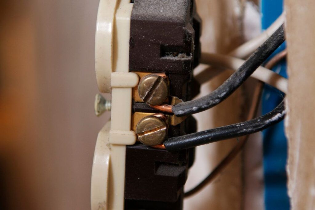
The line and load outlets have a special difference in terms of the GFCI outlets.
GFCI means Ground Fault Circuit Interrupter.
These outlets trip whenever they sense danger and prevent short circuits and electrocution.
The GFCIs have two screw terminal pairs. One pair is marked as LINE, and the other as LOAD.
Connecting to the line terminals causes the outlet to provide GFCI protection only for the outlet.
Connecting the line and load terminals with two electrical cables or two sets of pigtail wires will protect the outlet and other standard outlets downstream in the circuit.
Service entry and main panel
The line side of the electric meter will receive the incoming feed from the utility company.
The power will exit the meter on the load side and feed the disconnect or the electrical panel on the line side.
Importance of differentiating between line and load wires in electrical works
As mentioned earlier, the line wire carries the current from the power source and transfers it to the outlet.
The outlet will carry this current through the load wire to the connected devices.
There is another third wire called the ground wire.
It is usually green or bare copper wire.
The ground connection works with the line wire to prevent fatal electric shocks during a short circuit.
A poor connection between the line and load wires of the GFCI socket will make the circuit breaker useless and create a shock hazard.
Another situation where the GFCI becomes useless is mixing up the two wires.
If you are unaware of the wire identification, you may mix up the load and line wires in the circuit as a beginner.
As a result, the GFCI will no longer be able to protect your breakers or outlets.
The GFCI has a breaker that interrupts the current and trips off during a sudden surge.
Interchanging the load and line wires will eliminate this interruption.
Though interchanging the wires does not affect the outlet, the protection becomes ineffective.
Swapping the wires makes a direct connection to the appliance, which makes the switch useless.
That is why it is very important to identify the wires and understand the differences before attempting any electrical wiring connections.
How to identify the line and load wires in the electrical circuits
There are multiple ways to identify the line and load wires.
Generally, the black insulated wire is the line wire, and the load is the red wire.
Many other ways exist to identify them, like the wire size, placement, or with a voltage tester, multimeter, and neon screwdriver.
Below, I have described how I have attempted several methods to identify the line and load wires:
Wire colors
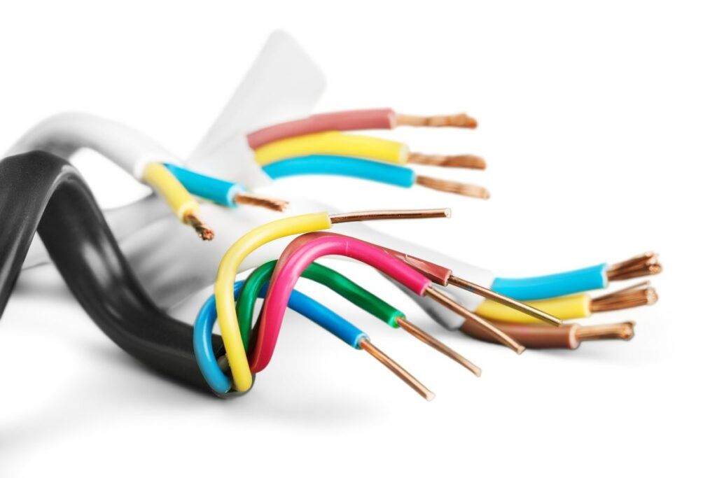
Specifying both wires through the color codes is the simplest method.
The wires are insulated with rubber to save us from electrical shocks.
The rubber insulation comes with a color to differentiate the wires.
The black insulated wires are typically the line wires, and the red insulated wires are the load wires.
But the problem occurs when the colors are the same for both wires, or the colors will be interchanged because the color doesn’t have anything to do with the wire.
So, how will you identify the wires? Look for their positions.
Wire positions
The line and load wires have different positioning due to their functions.
Since the line wire supplies power, it will typically be at the switch’s bottom.
On the contrary, the load wire will be at the top of the switch.
Here also arises confusion if:
- You are unaware of which part of the switch is the top or the bottom
- The wires are not connected to the switch.
So how will you accurately identify them? The next few parts will elaborate.
Using a voltage tester
Using a voltage tester will help you identify the accurate wire.
A non-contact voltage tester will make a beeping sound or illuminate light near electricity or voltage.
Only the line wire will carry the current when idle or the power is off.
Once the voltage tester touches the energized wire, it will beep or light up.
I always prefer a non-contact voltage tester to identify any wires.
They are safe, and you don’t need to touch any wires.
To use a voltage tester properly:
- Wear insulated gloves, turn off the switch, and unscrew the outlet’s cover plate.
- Turn the voltage tester on and pass it to the switch’s bottom and top terminals.
- Once the voltage tester contacts the line wire, it will beep or illuminate, while there will be no beep or lighting near the load wire. When the switch is off, only the line wire will carry current.
- If there is any third wire, green or white, it will be the ground or neutral wire. These wires, too, won’t give any reading.
Using a multimeter
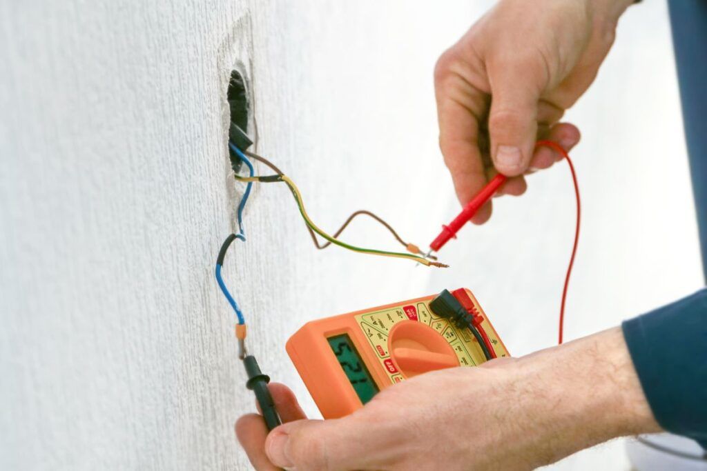
Using a multimeter is another way to receive accurate results about wire identification. But here, you have to touch the wire insulation.
Here are the steps:
- Turn off the power at the breaker.
- Set your multimeter to the highest voltage. Mostly, it is 250 VAC.
- Touch the multimeter’s black probe to the ground wire and use the red probe to test the wires.
- Touch the red probe with the black wire and then the red wire.
- The one wire that shows a voltage of 120V or 240V is the line wire. The other wire that does not show any voltage is the load wire.
- After turning the power off, only the line wire carries voltage, not the load wire.
Using a neon screwdriver
You can use a neon screwdriver if you do not have a voltage tester or a multimeter.
It works similarly to the voltage tester.
Once the screwdriver contacts the line wire, it will light up or beep.
Below are the steps:
- Turn off the power at the circuit, wear insulated gloves, and unscrew the electrical outlet.
- Connect the wires to the tester screwdriver from the top and bottom terminals in the outlet.
- You can also unscrew the wires to connect the wires directly to the tester or touch the metal end of the screwdriver with the terminals.
- Place your thumb on the screwdriver’s top and let the metals contact for a reading.
- A glowing light or a beeping sound indicates a line wire, whereas no light or beeping means it is the load wire.
Common mistakes to avoid when working with line and load wires

Sometimes beginners will make mistakes while attempting electrical wire connections.
Working with line and load wires can be dangerous. So, you must avoid making the following mistakes:
- Most people forget to turn off the circuit. Before you start working, turn off the circuit and confirm that no power is running with a voltage tester or multimeter.
- Always use wire compatible with the circuit and can carry the current running through it.
- You must identify the load and line wires. The load wires may not carry current after turning off the circuit, but the line wire carries. Accidentally touching them can shock you.
- Avoid mixing up the line and load wires, especially in a GFCI. Mixing them will deactivate the protection provided by the GFCIs.
- Swapping the line and load wire connections also makes the line wire directly connected to the outlet or the appliance. As a result, the switch becomes useless and disturbs the circuit.
- Ground the wire connections properly. Without grounding, you can receive electric shocks during a short circuit.
- Avoid reverse polarity. The wires must be connected to their respective terminals.
- Avoid overloading the circuit to prevent breaker tripping and fire hazards.
- Failing to follow the local code causes safety hazards. Whatever connections and installations you make, obey the local building code for safety and compliance.
Just because you can do things yourself doesn’t mean you should avoid an expert’s advice. You must always consult an electrician before approaching any electrical work yourself.
How to connect the line and load wires to the electrical circuits?
The line or live wires will have three wires – hot, neutral, and ground.
The hot and neutral wires will be insulated, and the ground will usually be bare. But sometimes, it is insulated with green rubber.
The load wire will conduct the electricity from the device to the other connected devices in the house.
The load wires also have three wires – hot, neutral, and ground.
The load wire becomes a line wire when it reaches the next outlet device in the circuit breaker.
The pattern continues.
Connecting the load and line wires depends on which circuit you connect them to and its components.
Below are some general steps you can follow for wiring:
- Turn off the breaker to avoid electrocution and check for power running with the help of a voltage tester.
- You must identify the line and load wires to connect them if idle. The line will carry the current from the main power source to the circuit, whereas the load wire will carry the current from the circuit to your appliance.
- If the wires are idle, use a voltage tester, multimeter, or neon screwdriver to identify them. The line wire will have voltage despite being disconnected.
- Once you have identified the wires, strip the insulation of both the wires around ½ inch with a wire stripper.
- Connect the wires properly based on the circuit type and the internal components. For example, if the circuit is for a simple switch, connect the line wire to one switch terminal at the bottom and the load wire to the other terminal at the top. For an outlet circuit, connect the line wire to the brass terminal and the load wire to the silver terminal. In a light fixture, connect the line wire to the fixture’s black/wire and the load wire to the fixture’s white wire.
- Once the wire connections are complete, secure the connections with wire nuts or connectors.
- Turn on the power supply and check the connections you have made in the circuit. If it doesn’t work, turn off the power and recheck the connections. If you have doubts, call an electrician.
Types of electrical devices and equipment that utilize line and load wires
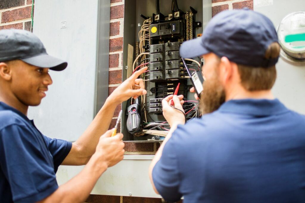
The line and load wires are used in various appliances and devices, and below is a small list of them:
- Circuit breakers
- Switches
- Outlets
- Light fixtures
- Motors
In these appliances, the line wires connect to the power supply to carry power.
The load wire will take this power to the connected devices.
In the motors, the line wire connects to the power supply, and the load wire connects to the motor for energy to drive.
Line and load wires in the residential vs. commercial electrical systems
You can use line and load wires for both commercial and residential purposes.
In both the electrical systems, the line wire helps bring in the power from the main power supply.
In the residential electrical system, the load wire provides power to your house’s different house appliances, lights, and other devices.
Besides, the residential systems’ voltage is generally 120V and rarely 240V.
So, the wirings are meant to handle the lower loads in the houses.
In commercial systems, the load wire provides power in a wider range, like HVAC systems, computers, machinery, servers, etc.
The line and load wiring in commercial electrical systems are made to handle higher loads with 208V to 480V.
Due to the higher loads, the wiring is more complicated than the residential.
Whatever the electrical system, you must properly plan the wiring for safety and compliance.
The wiring connections you make must follow the rules and regulations of the local building codes.
Proper safety precautions when handling line and load wires
As a beginner, if you decide to handle the line and load wires, you need to follow a few precautions for safety purposes:
- Always plan what repair you will do and what tools you need.
- Use a wooden ladder instead of metal if you need to climb higher.
- Use rubber-insulated tools for electrical work.
- Always turn off the switch at the circuit and check with a voltage tester to confirm that no power is running.
- Refrain from overloading your outlet with too many heavy appliances.
- If you have stripped any wires, ensure no wires remain exposed as it increases electrocution risk. Always cover them with wire nuts or connectors and secure them with wiring or masking tape.
- Read the electrical hazards and memorize the repairing techniques before attempting them.
- Know the difference between the wires. Use a voltage tester.
- Whatever wiring connections you plan to make must be done by following your region’s building codes.
- Wear protective gear, like goggles, insulated gloves, and rubber shoes.
- Ensure the wall, floor, hands, or surrounding areas are not wet.
- If you are in doubt, contact a professional for help.
Final thoughts
While working with electrical wiring, identifying the wires is crucial to avoid dangerous mistakes. The line wires carry power from the power supply to the outlet. The load wire carries this power from the outlet to the connected devices. You can identify the wires by their color and position. The line wires are black and connected at the bottom of the switch terminal.
The load wires are red and connected to the top of the terminal. Conditions like the same wire colors or idle wires make identification challenging. That is when the voltage testers, multimeters, and neon screwdrivers come to the rescue. The line wire always carries current despite turning off the circuit. But the load wires won’t have any voltage.
So, whenever you touch the line wire with the multimeter or screwdriver or bring the voltage tester close, the multimeter shows readings. The screwdriver and voltage tester beep or illuminate. Follow the safety precautions and avoid mistakes for a safety wire installation.
What happens if I swap the load and line wires?
The normal switches won’t have a problem as they supply power and stop the voltage to a device. In a GFCI, its protection quality becomes useless.
Is the line wire hot or the load wire?
The line is always hot as it will carry current from the main power supply. The load wires become live only after the switch is turned on to pass current from the line wire.
Reference: Electrical Wiring Wikipedia
